![]() DesignFiX - Module Anchor Design
DesignFiX - Module Anchor Design
|
|
The anchor design in DesignFiX is based on the European Technical Guideline published by the EOTA (European Organisation for Technical Approvals: Guideline for European Technical Approval of Metal Anchors for Use in Concrete (ETAG 001). Brussels 1997, 1998, 2002). The detailed design rules for both, mechanical anchors as well as chemical anchors are also covered by the guideline (European Organisation for Technical Approvals: Guideline for European Technical Approval of Metal Anchors for Use in Concrete (ETAG 001). Annex C: Design Methods for Anchorages. 3. Amendment, Brussels, August 2010) and (European Organisation for Technical Approvals: Guideline for European Technical Approval of Metal Anchors for Use in Concrete (ETAG 001). Technical Report TR 029: Design of bonded anchors. Brussels, September 2010). ETAG 001, Annex C and TR 029 use the so-called CC-Method (Concrete Capacity Method) which is based on a proposal by Fuchs (Fuchs, W.: Ableitung eines Vorschlags zur Bemessung von Befestigungen für die Verbindung von Stahl- und Betonbauteilen. Bericht 02/1991/1, Zeichen Fu 200/2-1, Deutsche Forschungsgemeinschaft, Bonn, 1991 [in German]) and (Fuchs, W.; Eligehausen, R.; Breen, J. E.: Concrete Capacity Design (CCD) Approach for Fastening to Concrete. ACI Structural Journal, Vol. 92 (1995), Nr. 1, S. 73-94).
At the ultimate limit state it shall be shown that the value Ed of the design actions does not exceed the value Rd of the design resistance:
Ed ≤ Rd
The value of the design actions may be either obtained from national regulations or, in their absence, from EN 1991 (EN 1991:2010: Eurocode 1, Actions on structures). The design value of the resistance is calculated as follows:
Rd = Rk / γM
The characteristic resistance of a single anchor or an anchor group is obtained according to ETAG 001, Annex C and TR 029 respectively and the partial safety factors for the resistance is given in the corresponding European approval. |
ETAG 001, Annex C and TR 029 permit single anchors and fastenings with two, three, four, six and eight anchors (any load direction, tension and/or shear loads) provided that the edge distance in all directions is c ≥ 10 ∙ hef and c ≥ 60 ∙ d (the greater of both values governs, hef = anchorage depth of the post-installed fastener, d = diameter of the anchor bolt or thread diameter, for anchors with internal thread d = outer diameter of the anchor). If no shear loads and/or torsion moments act on the fastening the configurations mentioned above are also permitted with small edge distances, although the minimum distances given in the European approval must be observed. If shear loads and/or torsion moments act on the fastening and the conditions c ≥ 10 ∙ hef and c ≥ 60 ∙ d are not met then only single anchors or groups with two or four post-installed anchors are permitted. |
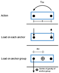
The loads acting on an anchor plate or a fixture (tension and compression forces, shear loads, bending and torsion moments) shall distributed to tension and shear forces acting on the individual anchors of a group. Friction forces between anchor plate and concrete surface due to compression forces or bending moments are not considered in the verification for shear loads. The determination of the tension forces acting on an individual anchor of an anchor group is carried out in DesignFiX in accordance with ETAG 001, Annex C and TR 029 based on the theory of elasticity. A linear distribution of strains across the anchor plate or fixture and a linear relationship between strains and stresses is assumed (Figure 1).
This requires a rigid anchor plate or fixture that does not deform significantly. The plate or fixture should remain elastic under the design actions and its deformation should be compatible with the fastener’s displacement. In addition, further assumptions are valid according to ETAG 001, Annex C and TR 029:
1)The stiffness of all anchors is equal and corresponds to the modulus of elasticity of the steel. The modulus of elasticity of the concrete may be taken from EN 1992-1-1:2004 (EN 1992-1-1:2004: Eurocode 2, Design of Concrete Structures - Part 1-1: General Rules and Rules for Building). In DesignFiX, as a simplification, the modulus of elasticity of concrete is assumed as Ec = 30 000 N/mm² independent of the concrete strength. 2)Anchors in the area of compression below the base plate do not take tension forces.
ETAG 001, Annex C and TR 029 contain no detailed information on the verification of a stiff base plate. Nevertheless, this verification is very important. In case of a non-rigid base plate and acting bending moment(s) the resultant of the compression forces below the base plate moves into direction of the welded profile, the lever arm of the internal forces is smaller than assumed in the calculation and the tension forces on the individual anchors of a group are higher than assumed in the theory of elasticity.
The design of the base plate is carried out in DesignFiX using a Finite Element Program for the determination of the plate thickness. It is explicitly pointed out that the anchor plate design is based on a proof of stresses and allows no direct statement about the stiffness of the base plate. The proof of the necessary stiffness in order to fulfil the requirements of the theory of elasticity has to be done separately or it must be ensured by suitable measures (e. g., by welded stiffeners) that the conditions of the theory of elasticity are met.
DesignFiX determines the tension forces on the individual anchors of a group due to normal forces and bending moments iteratively. In case of uni-directional bending combined with a normal force the size of the compression zone below the anchor plate and the edge strains are varied until the sum of the normal forces (N) and the bending moments (Mx) result in zero. In case of oblique bending, in addition, the inclination of the neutral axis must be varied until the sum of the moments in the second direction (My) results also in zero.
Information: Inconclusive iteration In certain rare situations there is a possibility that the iteration is inconclusive. This can e.g. happen when high compressive forces act upon the base plate. This leads to high actions and small anchor forces. This can also be the case when the anchors are positioned extremely unsymmetrically in two directions on the base plate or when the neutral axis is in close proximity of one anchor. In this situation the force in the anchor alternates from tension load to no tension load. After a predetermined number of iteration steps DesignFiX automatically stops the iteration, followed by a corresponding error message.
Shear loads on the anchors due to shear forces and/or torsion moments acting on the anchor plate are also determined based on the theory of elasticity. It is assumed that all anchors within a group have the same stiffness. This assumption is justified because ETAG 001, Annex C and TR 029, Section 1.1, permit in an anchor group only anchors of the same type, size and anchorage depth. Furthermore, it is assumed that the diameter df of the hole in the base plate or fixture does not exceed the values according to Table 1.
Table 1:
1) Bolt bears against the base plate or fixture 2) Sleeve bears against the base plate or fixture
These values are printed in the results.
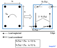
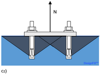
The distribution of the shear loads on the individual anchors of a group depends on the mode of failure. Figure 2 shows the distribution of a concentric shear load that is acting in the centre of gravity of the anchors for the failure modes “steel failure” and “pry-out failure (concrete failure on the opposite side of the load, compare Figure 12)”. If the diameter of the hole in the base plate or fixture according to Table 1 is met all anchors of the group take up shear loads. In absence of torsion moments the shear forces acting on the individual anchors of the group are calculated from the acting shear load divided by the number of anchors (Figure 2a) to 2c)). In case of torsion (Figure 2d)) the shear forces acting on the individual anchors are determined from the torsion moment, the polar inertia moment and the distance of the respective anchor to the centre of gravity of the group.
If the hole diameters df in the base plate exceed the values of Table 1, the design method is only valid if the annular gap between the anchor and the fixture is filled with mortar of sufficient compression strength or eliminated by other suitable means (compare ETAG 001, Annex C, section 4.2.2.1).
Due to their thread diameter, concrete screws usually require larger hole diameters than given in Table 1. The ETAs then differentiate between the following three cases:
1)The relevant ETA contains the note: The design method according to ETAG 001, Annex C, Section 4.2.2 also applies to the hole diameters df specified in the annexes.
2)The relevant ETA contains the note: The conditions in ETAG 001, Annex C, clauses 4.2.2.1a) and 4.2.2.2b) are not met, as the hole diameters in the fixture are greater than the values in Annex C, Table 4.1. Therefore, for fastenings with more than one anchor, the characteristic resistance of the group for steel failure VgRk,s should be limited to 2 · VRk,s of a single anchor.
3)The relevant approval does not contain any information about the hole diameters.
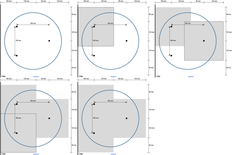
Anchors close to an edge and subjected by a shear load acting perpendicular to the edge fail by “concrete edge failure” (compare Figure 12b). In this case only the most unfavourable anchors (anchors close to the edge) take up shear loads (Figure 3). Because of the brittle concrete edge failure the displacements at ultimate load are relatively small. Due to the hole clearance between anchor and attachment, it is not sure whether the deformations of the anchors are sufficient to guarantee a load transfer to all anchors of the group before concrete edge failure occurs. Therefore it is assumed that only the fasteners close to the edge take up shear loads. This corresponds to the case that after installation the anchors close to the edge are in contact with the base plate while the anchors remote from the edge are without contact (Figure 4).
|
||||||||||||||||||||||||||||||||||||||||||||||||||||||||||||||||||||||||||||
|
|||||||||||||||||||||||||||||
|
Table 2 summarizes the required verifications for mechanical post-installed anchors under tension load:
Table 2: Required verifications for mechanical post-installed anchors under tension load
1)If pull-out/pull-through does not occur then this is stated in the corresponding European approval and the verification is not required. 2)Verification for splitting is not required if the edge distance in all directions is c ≥ 1,2 ∙ ccr,sp and the thickness of the concrete component is h ≥ 2 ∙ hef or if the selected anchor is suitable for use in cracks, the verification is carried out for cracked concrete and a reinforcement is present that limits the crack width to wk ≈ 0,3 mm, taking into account the splitting forces introduced by the anchors. The values ccr,sp are given in the European approval.
As already mentioned, chemical post-installed anchors will not fail due to pull-out/pull-through but due to combined pull-out and concrete failure. Table 3 summarizes the required verifications for chemical post-installed anchors under tension load:
Table 3: Required verifications for chemical post-installed anchors under tension load
1)Verification for splitting is not required if the edge distance in all directions is c ≥ 1,2 ∙ ccr,sp and the thickness of the concrete component is h ≥ 2 ∙ hmin or if the selected anchor is suitable for use in cracks, the verification is carried out for cracked concrete and a reinforcement is present that limits the crack width to wk ≈ 0,3 mm, taking into account the splitting forces introduced by the anchors. The values ccr,sp and hmin are given in the European approval. |
Generally, it cannot be predicted which of the possible failure modes under tension load is decisive for the design. Therefore DesignFiX carries out the verifications for all failure modes given in Table 2 (mechanical post-installed anchors) and Table 3 (chemical post-installed anchors).
|
|||||||||||||||||||||||||||||||||||||||||||||||||||||||||||||||||||||||||||||||||||||||||||||||||||||||||||||||||||||||||||
Generally, it cannot be predicted which of the possible failure modes under shear load is decisive for the design. Therefore DesignFiX carries out the verifications for all failure modes given in Table 4.
|
|||||||||||||||||||||||||||||||||||||||||||||||||||||||||||||||||||||||||||||||||||||||||||||||||||||
Fastenings simulateously subjected to tension and shear loading shall be varified according to ETAG 001, Annex C and TR 029. A distinction is made between two cases: Steel failure governs under tension and shear: One of the two following equations shall be satisfied:
Other failure modes decisive: If concrete failure governs at least one of both verified load directions (tension load: pull-out/pull-through (mechanical anchors), combined pull-out and concrete failure (chemical anchors), conical concrete break-out or splitting; shear load: pry-out or concrete edge failure), then one of the two following equations shall be satisfied:
In practice, the rules for the verification of the interaction are often interpreted differently. If steel failure governs for tension and shear load, some anchor design programs available on the market satisfy only the two equations that apply to this application. The verification for the other applications (other failure modes decisive) is completely omitted. This approach is not conservative in cases where the use of the capacity for the concrete failure modes is only slightly lower than for steel failure. E.g., if the use of capacity of a fastening for steel failure is
This phenomenon was described in the literature, e.g., Mallée, R.; Fuchs, W.; Eligehausen, R.: Design of Fastenings for Use in Concrete - the CEN/TS 1992-4 Provisions. Ernst & Sohn, Berlin, 2013. Therefore DesignFiX always superimposes all different uses of capacity (see Table 5). Generally both interactions are verified: The non-linear (Table 5, interaction 1) and the linear (Table 5, interaction 2). The lower use of capacity governs.
Table 5: List of the verification for interaction carried out by DesignFiX
|
||||||||||||||||||||||||||||||
Guideline ETAG 001 of the EOTA (European Organisation for Technical Approvals: Guideline for European Technical Approval of Metal Anchors for Use in Concrete (ETAG 001). Brussels 1997, 1998, 2002) describes in the Technical Report TR 045 a design method for anchors for use in concrete under seismic actions (European Organisation for Technical Approvals: EOTA Technical Report TR 045: Design of Metal Anchors for Use in Concrete Under Seismic Actions. Brussels February 2013). The design method covers connections between structural elements (Type ‘A’) and attachments of non-structural elements (Type ‘B’). It applies to mechanical and chemical anchors whose suitability for seismic loads is demonstrated by a European Technical Approval (ETA). The Technical Report is intended for safety relevant applications in which a failure of the fastening will result in collapse or partial collapse of the structure, cause risk to human life or will lead to significant economic loss. The provisions do not apply to the design of anchors located in critical regions of the structure where concrete spalling may occur or where wide cracks due to yielding of the reinforcement cannot be excluded (e. g., in plastic hinge zones). The length of these critical regions is defined in EN 1998-1:2004 (EN 1998-1:2004: Eurocode 8: Design of Structures for Earthquake Resistance - Part 1: General rules, seismic actions and rules for buildings. European Committee for Standardization (CEN), Brussels, 2004).
At the ultimate limit state (ULS) it shall be shown that the design action Ed does not exceed the design resistance Rd. The anchor forces shall be derived using appropriate combinations of actions for seismic situations as recommended in EN 1990 (EN 1990: Eurocode - Basis of Structural Design. European Committee for Standardization (CEN), Brussels). The partial safety factors for actions shall also be in accordance with EN 1990 and the partial safety factors for material under seismic actions should be identical to the corresponding values under static or quasi-static loading according to ETAG 001, Annex C and Technical Report TR 029. In the damage limitation state (DLS) it shall be shown that the displacement of the anchor is not larger than the admissible displacement. The admissible values depend on the application and shall be evaluated by the design engineer.
For the design the following general principles are applied in accordance with Technical Report TR 045, Section 5.1: •Anchors used shall meet all applicable requirements for non-seismic applications. •Only anchors shall be used that are suitable for use in cracked concrete and for seismic applications (see relevant European Technical Approval (ETA)) •Generally, the concrete is assumed to be cracked. Technical Report TR 045 permits to assume non-cracked concrete if it is demonstrated that the concrete remains non-cracked during the seismic event. Since this evidence will not be possible as a rule, DesignFiX always considers cracked concrete. •An annular gap between anchor and attachment should be filled by mortar of sufficient strength or eliminated by other suitable means such as snap rings. Only for fastenings of non-structural elements in minor critical applications an annular gap is permitted provided that its effect on the resistance of the fastening is considered by means of the factor •Displacement of the anchor shall be accounted for in the design. Therefore the ETA gives values for the displacements under tension and shear for the performance category C2 in the ultimate limit state (ULS) and in the damage limitation state (DLS). •Loosening of the nut or screw shall be prevented by appropriate measures. •Shear loads with lever arm (e. g. thick levelling grout layers or stand-off installations) are not covered by TR 045.
Furthermore TR 045 permits a design for earthquake actions according to the same rules that are used for static and quasi-static loads if the seismic portion of the tension and shear load is < 20%. This provision is not used in DesignFiX.
Technical Report TR 045 distinguishes the two seismic performance categories C1 and C2. Seismic performance category C1 provides anchor resistances at ultimate limit state (ULS), while performance category C2 provides anchor resistances at ultimate limit state as well as displacements at damage limitation state (DLS) and ultimate limit state (ULS). The requirements for the C2 category are higher than for category C1. The performance categories of the respective anchor are given in the corresponding ETA.
Table 6 shows the recommended seismic performance categories as a function of the seismicity level and the importance class of the building. The seismicity level is defined as function of the design ground acceleration ag on Type A ground and the soil factor S according to EN 1998-1:2004. The value ag and the product ag ∙ S used in a member state to define thresholds for the seismicity classes may be found in the National Annex of EN 1998-1:2004 and may differ from the values given in Table 6. Furthermore, the assignment of the seismic performance categories C1 and C2 to the seismicity level and importance class of the building is in the responsibility of each member state and may also differ from Table 6.
Table 6: Recommended seismic performance categories for anchors according to TR 045
•Capacity design in accordance with TR 045, Section 5.3a1 •Elastic design in accordance with TR 045, Section 5.3a2 •Design with requirements on the ductility of the anchors in accordance with TR 045, Section 5.3b
With capacity design the anchors are designed for the maximum load to be resisted by the attachment. In this way the fastening is protected against overloading and brittle concrete failure is permissible.
With elastic design the anchors are designed for the maximum load obtained from the design load combinations according to EN 1998-1:2004 that include seismic actions EE,d at ultimate limit state (ULS). Elastic behavior of both, the fastening as well as the structure is assumed. Uncertainties in the model to derive seismic actions on the fastening shall be taken into account.
With design for ductile behavior of the anchors additional ductility requirements shall be met. Thus, steel failure of the anchors is ensured and brittle concrete failure can be excluded with high probability. Standard commercial anchors do not meet the ductility requirements. Therefore, the design option “Ductile steel failure” is not considered in DesignFiX.
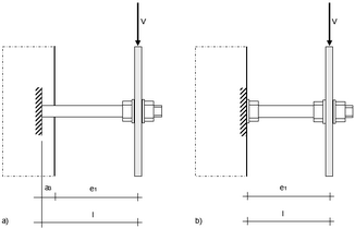
The anchors are designed for the maximum load that can be transmitted to the anchors by the attachment. Enter in the 3D-model the maximum tension- and/or shear loads that cause yielding of the attachment welded to the anchor plate (Fig. 41a) taking into account strain hardening and material over-strength or enter the maximum load that can be transferred to the fastening by the non-yielding attachment or the structure (Fig. 41b).
Enter in the 3D-model the maximum load obtained from the design load combinations that include seismic actions EE,d according to EN 1998-1:2004 at ultimate limit state (ULS) assuming an elastic behavior of the fastening and of the structure. Uncertainties in the model to derive seismic actions on the fastening shall be taken into account. For connections between structural elements (Type ‘A’) the action effects shall be derived according to EN 1998-1:2004 with a behavior factor q = 1.0. For attachments of non-structural elements the behavior factor is qa = 1.0. If action effects are derived in accordance with the simplified method given in TR 045, Section 5.5.4 with qa = 1.0 they shall be multiplied by an amplification factor of 1.5. If the action effects are derived from a more precise model this amplification factor may be omitted.
The design value of the effect of seismic actions EE,d shall be determined according to EN 1998-1:2004 and TR 045, Section 5.3. Additional requirements including vertical seismic actions acting on non-structural elements are provided in TR 045, Section 5.5. It shall be assumed that the maximum actions under tension and shear act simultaneously if no more accurate model is used.
For the design of connections between structural elements (Type ‘A’) the vertical component of the seismic action shall be taken into account according to EN 1998-1:2004, Section 4.3.3.5.2 (2) to (4) in cases where the vertical design ground acceleration avg is greater than 2.5 m/sec².
In addition to EN 1998-1:2004, Section 4.3.5.1 any beneficial effect of friction due to gravity loads should be ignored in the design of fastenings for non-structural elements.
Further important additions and alterations to EN 1998-1:2004, Section 4.3.5.2 regarding the seismic action effects are listed in TR 045, Section 5.5.4.
The required verifications for tension and shear loads are given in Table 7. As in modern standards, the design value of the actions is referred to as Ed while TR 045 uses Sd.
Table 7: Required verifications for earthquake under tension and shear
The partial safety factors for the material should be identical to the corresponding values for static and quasi-static loads. They are given in the relevant ETA.
The characteristic resistance NRk,seis (tension load) and VRk,seis (shear load) are calculated as follows:
The reduction factor
The reduction factor
Table 8: Reduction factor
The values for steel failure under tension and shear loads as well as for pull-out / pull-through failure (mechanical anchors) under tension loads are given in the relevant ETA ( In cases where tension and shear loads act simultaneously the following interaction verification is required:
The largest ratios
In accordance with TR 045, Section 5.7, the displacements of the anchors under an earthquake of performance category C2 shall be limited to required values δN,req(DLS) (tension load) and δV,req(DLS) (shear load) in order to meet the requirements of the functionality and assumed support conditions. This is especially important if rigid supports are assumed or if the fastening and the fastened element should still be functional after an earthquake. The required values of displacement depend on the specific application and shall be evaluated by the design engineer. DesignFiX compares these values with the displacements δN,seis(DLS) and δV,seis(DLS) given in the ETA. In cases where the ETA values are larger than the required displacements DesignFiX reduces the design values of the resistances as follows:
|
|||||||||||||||||||||||||||||||||||||||||||||||||||||||||||||||||||||||||||||||||||||||||||||||||||||||||
|
Online version: German | English


