Search DesignFiX Knowledge Base by Keyword
Curious #2: Characteristic resistance / embedment depth

In the post of February 8, 2016 it has been demonstrated that the characteristic resistance of injection anchors for splitting failure designed according to ETAG 001, TR 029, may decrease despite increasing embedment depth. The same phenomenon can also occur for combined pullout and concrete failure. This behavior also contradicts the expectations of users.
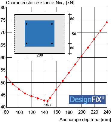
The figure shows the characteristic resistance of a group consisting of four injection anchors M16 in a narrow component for the failure mode combined pull-out and concrete failure as a function of the anchorage depth. The spacing of the anchor be s1 = 200 mm or s2 = 150 mm and the edge distance c = 80 mm, the component is 280 mm thick. The concrete is cracked and corresponds to class C20/25. The concrete component is normal (not dense) reinforced. The anchors are installed in dry/wet concrete and the application temperature is 40 °C (short term) or 24 °C (long-term).
The following characteristic bond strengths are given for the conditions described above in the approval (ETA) of the selected injection system:
Non-cracked concrete: τRk,ucr = 14 N/mm²
Cracked concrete: τRk,cr = 6 N/mm²
It can be seen that the characteristic resistance drops between hef = 80 mm and hef ≈ 146 mm and then rises continuously for greater depths. The decrease in resistance for small embedment is on the boundary of the characteristic axial spacing scr,Np according to ETAG 001, TR 029, Equation (5.2c) to a maximum value of scr,Np = 3 ∙ hef. The characteristic spacing is
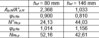
Up to an anchorage depth of hef = 437.2 / 3 = 145.7 mm, the limit to the maximum value of 3 ∙ hef is effective, i. e., the characteristic axial spacing increases linearly with the anchorage depth. Thereby, the ratio of the idealized fracture surfaces Ap,N/A°p,N and the factor ψs,Np to consider the effect of edges decrease (Table 1). This negative impact is not compensated by the linear increase of the characteristic resistance N°Rk,p of a single anchor and of the group factor ψg,Np. This reduces the resistance of the group of NRk,p = 52,16 kN to NRk,p = 42,61 kN.
 Table 1:
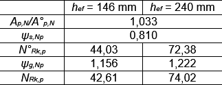
Between hef ≈ 146 mm and hef = 240 mm the limitation of the characteristic axial spacing is no longer effective, the spacing is with scr,Np ≈ 437 mm constant. The same also applies to the areas Ap,N and A°p,N and the factor ψs,Np. However, the characteristic resistance N°Rk,p of a single anchor rises and also the group factor ψg,Np increases (Table 2). Consequently, the characteristic resistance of the group increases. This is what the users expect.
 Table 2:
The limitation of the characteristic axial spacing scr,Np to a maximum value can cause unexpected results for small embedment depths, but also has advantages. Without limitation, the areas Ap,N and A°p,N and the factor ψs,Np would be constant also for embedment depths between hef = 80 mm and hef ≈ 146 mm. Only the resistance N°Rk,p of a single anchor would go up linearly with the anchorage depth and the factor ψg,Np would slightly increase. Under these assumptions the characteristic resistance of the group with hef = 80 mm would only amount to NRk,p = 20,92 kN instead of NRk,p = 52,16 kN. I. e., without the limitation the resistance would decrease with decreasing embedment depth (hef < 146 mm) and the rate of utilization would increase at constant load (compare: Mallée, R.: Anmerkungen zur Bemessung von Dübeln nach europäischen Regelungen (Comments on the design of anchors according to European regulations). Verlag Ernst & Sohn, Beton- und Stahlbetonbau, 2014, No. 10, pp. 699 – 712, in German). This behavior corresponds to the expectations of the user, according to which the resistance should increase with increasing embedment depth, but on the other hand causes at the same time compared to the current approach, a decrease in the load-bearing capacity at small embedment depths. (FiXCurious to be continued)


