Search DesignFiX Knowledge Base by Keyword
Tab – LOADS
LOADS
Edit attachment Edit geometry
This function opens the tabular input window in the program area 3D-Model.
The section design loads / characteristic loads is opened in the input window and all other sections are closed. With the lower part of the button you can alternatively open all sections of the window or close it. The input window offers an extremely practical and convenient alternative to entering the dimensions and loads.
The following values can be entered:
| epx , epy | Eccentricities of the load in positive/negative X- and Y-direction with respect to the centre of gravity of the attachment |
| NG , NQ , VxG , VyG , VxQ , VyQ , MxG , MyG , MxQ , MyQ , MzG , MzQ |
Characteristic values of the applied actions (normal and shear forces, bending and torsion moments) |
| NEd , VxEd , VyEd , MxEd , MyEd , MzEd |
Design values of the applied actions (normal and shear forces, bending and torsion moments) |
| γG , γQ | If characteristic values of the applied actions are selected: Partial safety factors for permanent loads (G) and variable loads (Q) |
Alternatively, these values can be entered directly in the corresponding input field of the 3D-drawing. A direct link exists between the input fields of the 3D-drawing and the input window. If the cursor is positioned in an input field of the 3D-drawing then the corresponding field in the input window is marked (hover effect) and vice versa. This makes it easier to navigate.
With the function Type of loading it can be defined whether the applied actions are design or characteristic values. Design values are used unchanged in the design while characteristic actions are per definition multiplied with the partial safety factors γG for permanent loads and γQ for variable loads. The partial safety factors can be entered in the input field Characteristic loads. In addition, you can define for characteristic loads with the function Display whether the actions shall be displayed in the 3D-Modell separately as permanent and variable actions (two numbers per action) or whether the sum ![]() shall be displayed. The sums are calculated taking into account the signs of the actions.
shall be displayed. The sums are calculated taking into account the signs of the actions.
LEVER ARM
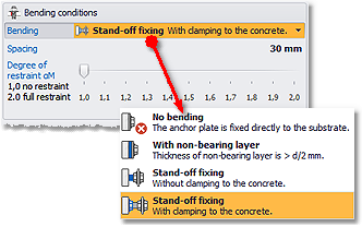
With the function Bending you can define whether the anchors are loaded by a shear loads with lever arm (bending) or not. We distinguish the following cases:
- No bending
- With levelling layer (i.e., a mortar layer with a thickness > d/2 is present between concrete surface and base plate or the compressive strength of the mortar is < 30 N/mm²)
- Stand-off fixing without clamping
- Stand-off fixing with clamping
The lever arm corresponds to the distance between the concrete surface and the fixture. The enlargement of the lever arm due to possible concrete spalling near the surface during drilling needs not to be considered. It is automatically considered by DesignFiX for stand-off fixings without clamping of the anchor against the concrete surface.
The value αM takes into account a possible restraint of the anchor on the side of the fixture. It shall be assessed in each individual case by the user and can be between αM = 1,0 (no restraint) und αM = 2,0 (full restraint). Please note that the fixture must be able to take up the restraint moment. In case of doubt it is recommended to assume αM = 1,0.
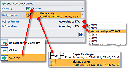
DESIGN FOR EARTHQUAKE (SEISMIC)
Note: This function is only available if at least one product installed is suitable for earthquake applications in accordance with ETAG 001, TR 045. When enabled, all other products will be hidden in the Product selection.
DesignFiX Information
If you select a product on the left side of the user interface then the logo of the manufacturer will be displayed at the right edge of the ribbon bar that contains further information. If DesignFiX finds a LiveUpdate then this information will appear at this point by means of an additional link.


